- Learn to use JLS, the tool we'll be using to simulate digital logic (and CPU components)
- Practice building more complex digital circuits
- Get a better feel for propagation delay and timing
Materials to Get Started:
- Click HERE to download JLS. (Depending on your OS and web browser, you may need to Right click and "Save As")
(By the way, JLS was created by Michigan Tech.'s Dave Poplawski. For more information, see the JLS webpage: http://www.cs.mtu.edu/~pop/jlsp/bin/JLS.html)
- Click HERE to download a JLS file for an RS-Latch built out of cross-coupled NOR gates. (Again, you may need to Right-Click and "Save As")
- You may want to start JLS and look at the on-line help and take a look at the Tutorials: for this assignment you'll need to know how to run simulations and modify existing circuits by adding gates and wires. After you've run JLS and gone through any tutorials that you'd like, get started on the homework.
The Assignment:
- Start JLS (it's a self-executing Jave Jar file. You should be able to run it by double clicking on it)
- Load the RSLatch.jls file provided
(File → Open. Select the file which hopefully you've saved somewhere convenient)
At this point you should see the circuit loaded into JLS and the screen should look like:
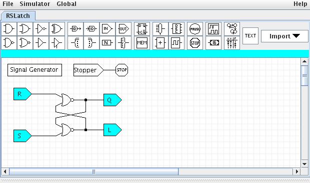
There are a three major parts to the circuit:- The circuit looks like:
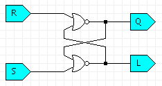
First the "inputs" to the gates are given a special symbol called an "input pin".
Notice that the picture indicates the direction of information flow as well as giving the input a name.
In the following case, the input is named "R" and it's an input (pointing into the wire/circuit):

The "outputs" are also given an "output pin". Again, this provides a name and makes the direction of information flow (out of the circuit) clear:

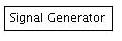
- The "Signal Generator":
 R  1 for 10
    0 for 50
    1 for 50
    0 for 50
    0 for 50
    0 for 50
    0 for 50
    0 for 50
    0 for 50
    0 for 50
    1 for 50
    0 for 50
    0 for 50
    0
end

S   0 for 10
    0 for 50
    0 for 50
    0 for 50
    0 for 50
    0 for 50
    1 for 50
    0 for 50
    0 for 50
    0 for 50
    1 for 50
    0 for 50
    0 for 50
    0
end

Stopper
    0 for 600
    1
end
This is a simple description of the inputs to my system. Each input is described in its own section, which begins with the input's name followed by a set of commands to control it and finally an "end".
So, the "R" signal is going to:
- 1 for 10 : turn
on (1) for 10 units of time (units don't matter, but I'll assume
nanoseconds).
(it's on from 0ns until 10ns)
- 0 for 50 : turn
off (0) for 50 units of time
(it's off from 10ns until 10+50=60ns) - 0 for 50 : turn
off (0) for 50 units of time
(it's still off from 60ns until 110ns) - .. etc.
- 0 : turn off
(0)
(Stay at a 0 until the simulation is done, time ends, or the computer dies)
NOTE: a easy error is leaving off this "final value", but it is essential.
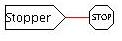
Notice that the "Stopper" signal is off for 600ns, then turns on.
The stopper isn't really part of the circuit, just a special way to tell JLS to end the simulation at 600ns.
- 1 for 10 : turn
on (1) for 10 units of time (units don't matter, but I'll assume
nanoseconds).
-
Notice that the "Stopper" is just connected to a special "STOP" gate:
- The circuit looks like:
- Turn on the "Simulator Window" via the menu: Simulator → Show
Simulator Window.
There's a horizontal control for making the Simulator window bigger - depending on how JLS looks, you may want to stretch it.
Mine looked like:
- Now "run" the simulation by clicking the green "start" button.
Notice that now the "simulation" window has updated to show some graphs of the inputs and outputs.
You should see something like this:
Move your mouse back and fourth over this window and you can see the "values" of each input and output at anyparticular time. - Questions Part A:
- In the original RS-Latch simulation:
- What are the values or S, R, Q, and L at time 265?
(Pay close attention to the order)
- What are the values of S, R, Q, and L at time 290?
- What has happened between these two times?
- What are the values or S, R, Q, and L at time 265?
- Modify the signal generator to cause both R & S to BOTH turn
on at t=460 and back off at t=510 and re-start the simulation.
- What are S, R, Q, and L at time 547?
- What are S, R, Q, and L at time 552?
- What has happened between these two times?
- What are S, R, Q, and L at time 547?
- In the original RS-Latch simulation:
- Create a D-Latch from the RS-Latch:
- Go to File → New (Name your new circuit. I called mine DLatch.
Creative huh?)
- "Import" the RS-Latch: File → Import and pick the RSLatch.jls.
(It'll ask for a "subcircuit name", I chose RSLatch again) - Create a proper D-Latch. Here are a few hints:
- Hit "ctrl-W" to start adding a wire. Go to where you want
the wire to begin and hit the mouse button to actually start it (like
at a gate input or output).
- If you want a wire to make a right angle, go to the place you want it to turn and hit the left mouse button
- If you want to connect a wire to something (like a gate),
move until the input or output connection glows green.
- If you want a wire to "end" without connecting to anything hit the left mouse button (to create an ending point) and then the right mouse button.
*** Notice that my D, Clock, and Q are highlighted. That's because I've right-clicked on each and selected "Watch". This is essential to see the results of running the simulation.
- Hit "ctrl-W" to start adding a wire. Go to where you want
the wire to begin and hit the mouse button to actually start it (like
at a gate input or output).
- Create the following test signal:
- D is on for 10ns
- D alterentes between off and on for 50ns each. Repeat this
cycle 9 times. (18 changes)
(Start in the "off" and have a total of 9 "ons" and 9 "offs") - Clock is on for 10ns
- Clock alternates between off and on for 175ns each. Repeat
this cycle 3 times.
- Run for a total of 1200 time units
- Questions Part B:
Carefully look at the result and print it to include with your home work.
Note that JLS sometimes doesn't show then entire signal unless you "scale" is using the scale option on the right. In my case I scaled it to "2".
Your printout should look something like this (NOTE: These are NOT the inputs I've asked you to use, just an example that shows the D, Clock, and Q from time=0 until time=1200):
Submission:
- Answers to questions in Part A:
- In the original simulation of the SR-Latch:
- What are the values or S, R, Q, and L at time 265?
(Pay close attention to the order)
- What are the values of S, R, Q, and L at time 290?
- What has happened between these two times?
- Modify the signal generator to cause both R & S to BOTH turn
on at t=460 and back off at t=510 and re-start the simulation.
- What are S, R, Q, and L at time 547?
- What are S, R, Q, and L at time 552?
- What has happened between these two times?
- What are S, R, Q, and L at time 547?